
By NBMOTOR Marketing
A shock absorber is easy to identify from the outside, but its real value is determined by what happens inside: hydraulic flow, valve response, sealing stability, heat management and repeatable manufacturing. For automotive aftermarket professionals, understanding these factors is essential when evaluating a replacement product, diagnosing a complaint or discussing specifications with a supplier.
This guide explains how automotive shock absorbers work, how the main designs differ, which manufacturing steps influence performance and which quality checks matter before a unit reaches the vehicle.
The suspension spring supports the vehicle and allows the wheel to move over road inputs. Left uncontrolled, however, the spring would continue to oscillate after each bump. The shock absorber—also called a damper—controls that motion.
As the piston rod moves, hydraulic oil is forced through carefully calibrated valve passages. The restriction creates a force that opposes suspension movement. Mechanical motion is converted into heat, which is then dissipated through the oil and outer body.
A correctly matched damper therefore contributes to:
A shock absorber does not carry out these functions in isolation. Tires, springs, bushings, mounts, wheel alignment and vehicle load all influence the final result.
Replacement dampers are supplied in several physical configurations. The correct format depends on the original suspension design:
These external forms should not be confused with the internal hydraulic architecture. The two most common internal layouts are twin-tube and monotube.
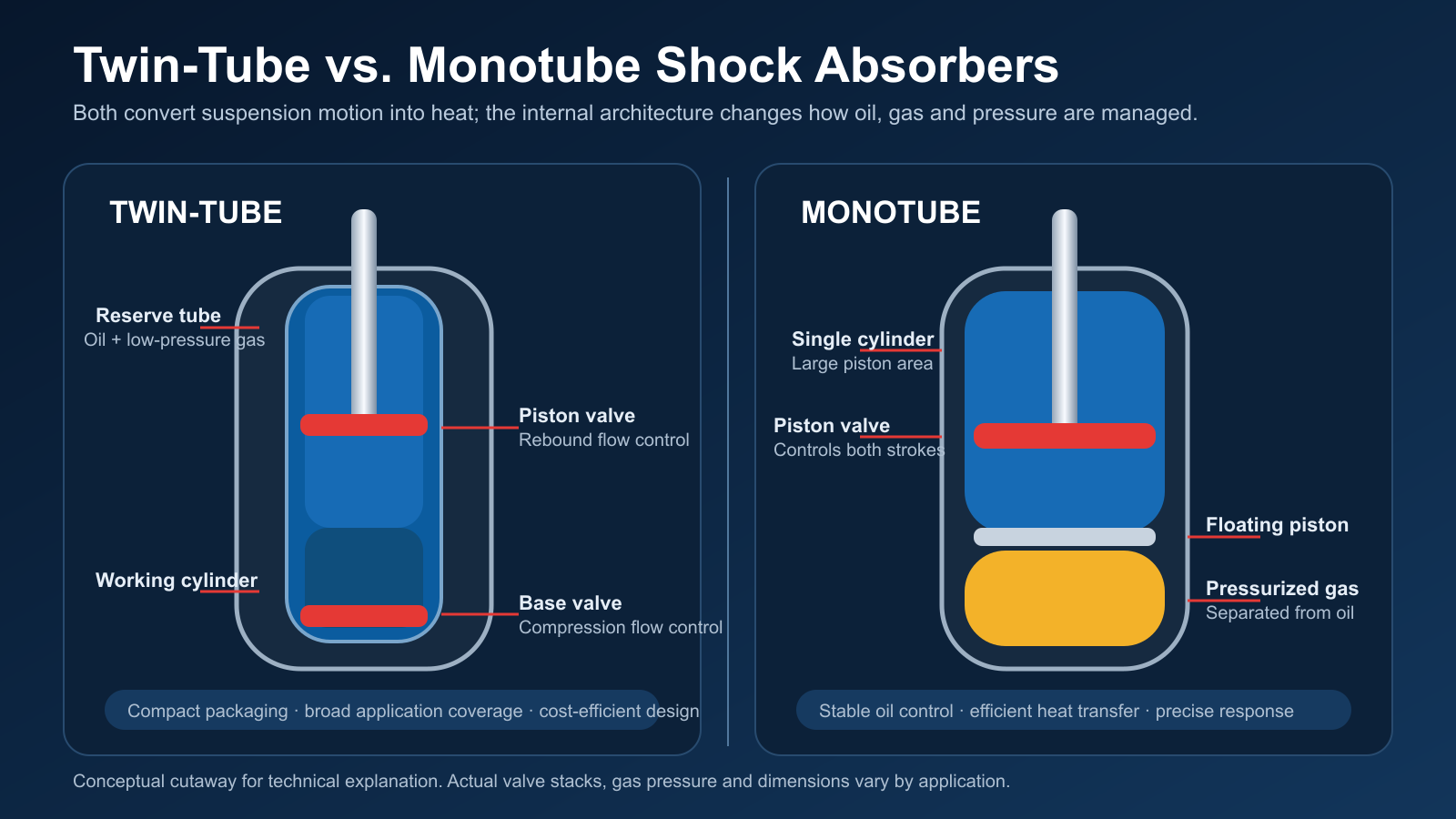
Conceptual cutaway. Actual dimensions, valve stacks and gas pressure vary by application.
A twin-tube damper uses an inner working cylinder and an outer reserve tube. The piston valve moves inside the working cylinder, while a base valve manages fluid exchange between the inner and outer chambers.
During compression, the entering piston rod displaces oil. Part of the oil flows through the piston valve and part passes through the base valve into the reserve chamber. During rebound, the piston valve provides the principal flow restriction while the base valve returns oil from the reserve chamber.
Twin-tube construction offers efficient packaging and broad application coverage. Its performance depends heavily on valve calibration, internal cleanliness, oil volume, gas control and assembly consistency.
A monotube damper uses a single pressure cylinder. The damping piston separates the working chambers, and a floating piston separates hydraulic oil from a pressurized gas chamber.
Because the oil and gas are physically separated, a properly designed monotube unit can maintain stable oil control under demanding operation. The larger working piston and direct contact between the cylinder and surrounding air can also support precise response and heat transfer. Packaging, ride targets, impact resistance, installation position and cost still need to be considered for each vehicle.
Neither architecture is automatically “better” for every application. The decisive question is whether the complete damper is correctly designed, manufactured and validated for the intended vehicle.
A damper operates in two directions:
The required force is not constant. It changes with piston speed and is shaped by bleed passages, orifices, discs, springs and valve geometry. Low-speed damping influences gradual body motions such as roll, pitch and weight transfer. Higher piston speeds occur during sharper road inputs and require adequate control without creating excessive harshness.
Manufacturers verify this behavior on a shock dynamometer. The resulting force-displacement and force-velocity curves reveal compression and rebound force, symmetry, hysteresis and consistency. Test velocities and temperature conditions must follow the drawing or customer specification; values from one application should not be copied to another.
Several parts have a disproportionate influence on service life and noise:
Shock absorber quality cannot be added only at final inspection. It is built through controlled component preparation and assembly.
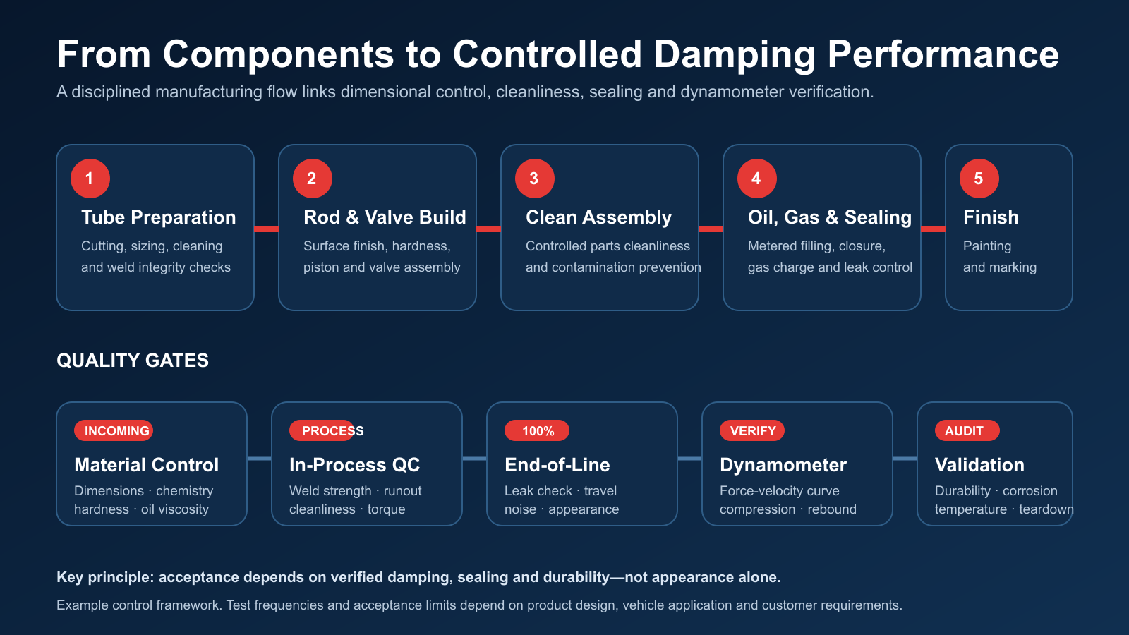
A typical production route includes tube cutting and sizing, welding, cleaning, piston-rod preparation, valve assembly, oil filling, gas charging, sealing, painting and final identification. The exact sequence varies by design, but five process controls remain especially important:
A robust inspection plan combines incoming checks, in-process control, end-of-line verification and periodic validation. Depending on the design and customer requirement, it may include:
Acceptance limits should always come from the approved product specification. A single force value, leakage limit or durability cycle count is not universal across passenger cars, commercial vehicles, performance applications and different damper architectures.
| Observed symptom | Possible damper-related causes | Other systems to inspect |
|---|---|---|
| Visible oil leakage | Seal damage, rod corrosion, guide wear, contamination or abnormal side load | Mounting alignment, damaged boot, impact damage |
| Excessive bouncing | Reduced damping force, internal valve damage, aeration or loss of oil/gas | Spring condition, tire pressure, vehicle load |
| Knocking or rattling | Internal looseness, worn guide, incorrect travel or damaged mounts | Top mount, bushings, stabilizer links, ball joints |
| Harsh ride | Excessive damping, high friction, incorrect application or binding | Tire specification, spring rate, bump stops |
| Uneven tire wear or instability | Weak or inconsistent damping may contribute | Alignment, tires, steering joints, bushings and wheel balance |
A light film around the seal area is not always equivalent to an active leak, and a ride complaint should never be diagnosed from the damper alone. Inspect both sides of the axle, verify mounting hardware and compare the vehicle condition with the service information for that application.
For distributors, workshops and private-label customers, a useful product review should go beyond catalog fitment. Confirm:
Always install with the correct tools and tightening procedure. On strut applications, spring compression work requires appropriate equipment and trained personnel. Where service instructions require axle-pair replacement, wheel alignment or new single-use fasteners, those requirements should be followed.
Technical requirements evolve. In China, QC/T 491-2018, Performance Requirements and Bench Test Methods for Automobile Shock Absorbers, replaced the earlier QC/T 491-1999 and QC/T 545-1999 documents and has been effective since January 1, 2019. For export programs, the applicable customer drawing, contractual specification and destination-market requirements must also be reviewed.
The practical conclusion is simple: a shock absorber is a calibrated safety-related chassis component. Reliable aftermarket performance comes from correct application engineering, clean and repeatable manufacturing, verified damping curves, sealing integrity and durability evidence—not from appearance alone.
NBMOTOR Marketing
Technical references: State Administration for Market Regulation: QC/T 491-2018; KYB technical information on monotube construction; KYB service information on shock and strut wear. This article is intended for general technical education. Product specifications and service procedures must be confirmed for each vehicle application.